G5RV to ZS6BKW modification
useable for 40, 20, 17, 12, 10 and 6m
my goal for this work:
In 2007 I installed an G5RV antenna to make my first steps on shortwave.
I was not very active after then but I worked something and mostly
running in WSPR , JT65 and PSK as SWL.
But something was wrong with this setup...now (after 6years)
I want to find out what it was...?
In the meantime my interest changed and I want to work a bit on the
WARC bands 12m and 17m and also on 6m so the G5RV should be modified to a
ZS6BKW antenna with very low money and time.
At first some antenna analysis using the MMANA software.
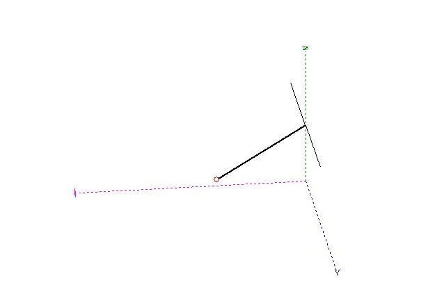
For the analysis of the ZS6BKW at around 6m height I used this setup.
The feeder line is made of 2 wires with small spacing to give around
450 Ohms line impedance.
After some steps of optimizations MMANA gave me
the following results of the planned ZS6BKW antenna.
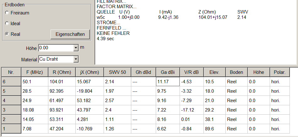
This looks not so bad . With the tuner it is possible to tune to
low SWR with moderate losses. But what is wrong with the "old" G5RV ?
Check the used materials ... it uses "GALVANISED IRON WIRE".
Simulate again to see if there is any difference.
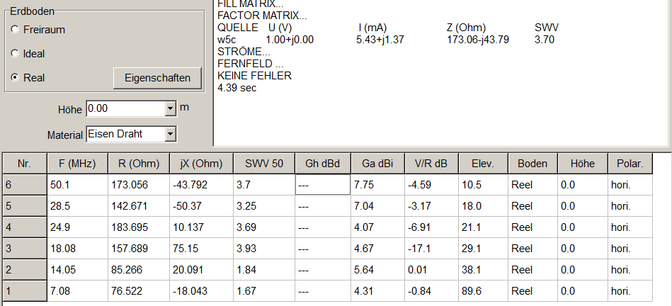
SURPRISE.... SURPRISE.....!!
for comparision
(SWR CHANGE and GAIN IN MAX LOBE)
This looks very dramatic but the real world losses of the old setup are lower
because not the complete antenna is made of galvanised iron wire.
The feeder line is made of copper (Wiremann CQ553 - 450 Ohms) so the losses are
only around 60% of the given value.
After this result I realized that it must be better to
use copper for the antenna wire.
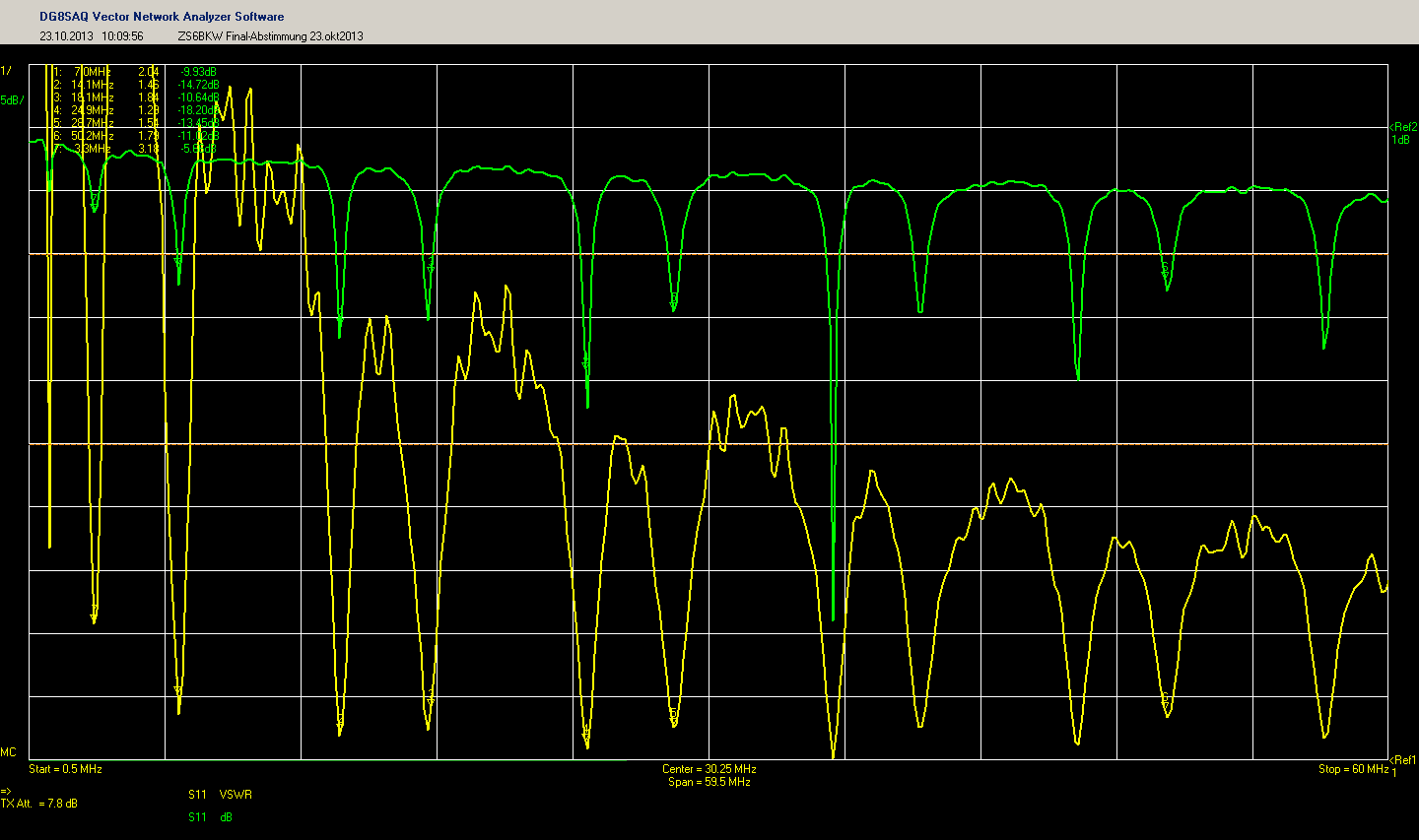
And here are the results after building and correct tuning of the antenna.
Note:
MMANA simulates longer values for the wires
"in my real world" they must be cut to around 3-5%.
The measurement was done on the antenna connector
in my shack (without tuner).
OCF- DIPOL for 40, 20 ,15 ,10 and 6m
my goal for this work:
Having a second antenna is nice to compare each other.
So a second wire for some bands is easy to made as an
OCF-dipole and with low budget. I used DG0KWs programm
for calculating windom antennas after DL1VU.
The main design parameters are given from the possible space
in my case about 21m.
"Stromsummenantenne" after DL1VU
antenna calculated for frequency: 50.1 MHz and 7 halfwaves
calculation for CW-Band: 50, 28, 24, 21, 18, 14, 10 MHz
antenna lenght: 20.81 m
velocity factor of wire: 0.95
calculated impedances for the amateur radio bands (examples)
(correct only for resonance!)
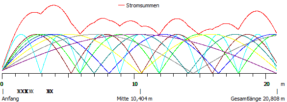
I used the combination with an feedpoint of 3.72m.
The overall length of the antenna is 20.81m.

| BAND | SWR (FE WIRE) |
SWR (CU WIRE) |
GAIN (FE WIRE) |
GAIN (CU WIRE) |
LOSS FE
vs CU |
| 40m |
1:1.67 |
1:1.26 |
4.31dBi |
6.62dBi |
2.31dB |
| 20m |
1:1.84 |
1:1.11 |
5.64 dBi |
8.16dBi |
2.52 dB |
| 17m |
1:3.93 |
1:2.4 |
4.67dBi |
7.22dBi |
2.55 dB |
| 12m |
1:3.69 |
1:2.57 |
4.07dBi |
9.16dBi |
5.09 dB |
| 10m |
1:3.25 |
1:1.97 |
7.04dBi |
9.75dBi |
2.71 dB |
| 6m |
1:3.7 |
1:2.14 |
7.75dBi |
11.17dBi |
3.42 dB |
This looks very dramatic but the real world losses of the old setup are lower
because not the complete antenna is made of galvanised iron wire.
The feeder line is made of copper (Wiremann CQ553 - 450 Ohms) so the losses are
only around 60% of the given value.
After this result I realized that it must be better to
use copper for the antenna wire.
And here are the results after building and correct tuning of the antenna.
Note:
MMANA simulates longer values for the wires
"in my real world" they must be cut to around 3-5%.
The measurement was done on the antenna connector
in my shack (without tuner).
| Frequency |
SWR |
| 7.0 MHz |
1:2.04 |
| 14.1 MHz |
1:1.46 |
| 18.1 MHz |
1:1.84 |
| 24.9 MHz |
1:1.29 |
| 28.7 MHz |
1: 1.54 |
| 50.2 MHz |
1: 1.8 |
OCF- DIPOL for 40, 20 ,15 ,10 and 6m
my goal for this work:
Having a second antenna is nice to compare each other.
So a second wire for some bands is easy to made as an
OCF-dipole and with low budget. I used DG0KWs programm
for calculating windom antennas after DL1VU.
The main design parameters are given from the possible space
in my case about 21m.
"Stromsummenantenne" after DL1VU
antenna calculated for frequency: 50.1 MHz and 7 halfwaves
calculation for CW-Band: 50, 28, 24, 21, 18, 14, 10 MHz
antenna lenght: 20.81 m
velocity factor of wire: 0.95
calculated impedances for the amateur radio bands (examples)
(correct only for resonance!)
| feed distance |
50MHz |
28MHz |
24.9MHz |
21MHz |
18MHz |
14MHz |
10MHz |
7MHz |
| 1.21m |
129 |
287 |
(335) |
409 |
(346) |
635 |
(489) |
1328 |
| 1.53m |
111 |
207 |
(338) |
323 |
(313) |
506 |
(444) |
1063 |
| 1.85m |
196 |
157 |
(368) |
259 |
(295) |
433 |
(419) |
920 |
| 2.28m |
405 |
100 |
(485) |
192 |
(292) |
349 |
(394) |
761 |
| 3.58m |
390 |
302 |
(448) |
110 |
(472) |
190 |
(390) |
491 |
| 3.72m |
296 |
351 |
(403) |
125 |
(525) |
177 |
(396) |
470 |
I used the combination with an feedpoint of 3.72m.
The overall length of the antenna is 20.81m.
But before we can start lets
verify the calculation results with MMANA.
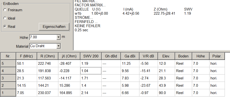
In the simulation you can see that the impedances are in a range of 117 to 230 Ohms.
To direct feed the coax line an impedance transformer of 4:1 is needed.
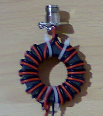
BUILDING THE 4:1 IMPEDANCE TRANSFORMER
My special goal was the use on the higher bands. So low loss and good match
of the transformer must be realized. I used an AMIDON FT240-61 core and made an
wideband 4:1 transformer with the information given by DG0SA (Wippermann balun).
I used 8 turns on the core. The 4:1 transformer looked like this...
For testing the transformer I checked it with the VNWA3
using a 200 Ohm load resistance.
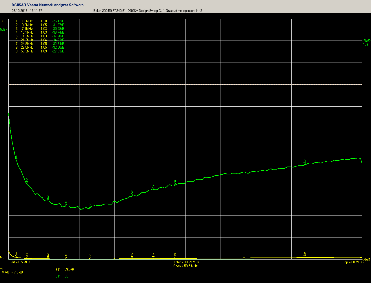
The SWR is below 1:1.1 in the range from 1.8 to 50MHz.
Now we need an additional current balun on the feedline.
I used an other core with some windings of RG316 teflon coax.
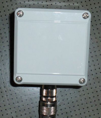
All is put together in the IP65 feeding box for the OCF-Dipole.
precutting the antenna wire and all is ready for test now...
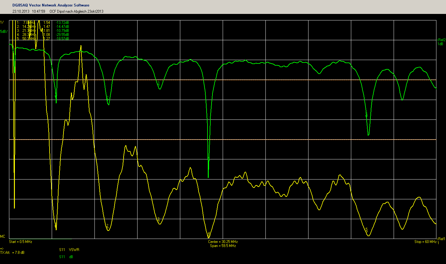
And here are the results after correct tuning of the antenna.
Note:
MMANA simulates longer values for the wires
"in my real world" they must be cut to around 3-5%.
The measurement was done on the antenna connector in
my shack (without tuner).
In the simulation you can see that the impedances are in a range of 117 to 230 Ohms.
To direct feed the coax line an impedance transformer of 4:1 is needed.
BUILDING THE 4:1 IMPEDANCE TRANSFORMER
My special goal was the use on the higher bands. So low loss and good match
of the transformer must be realized. I used an AMIDON FT240-61 core and made an
wideband 4:1 transformer with the information given by DG0SA (Wippermann balun).
I used 8 turns on the core. The 4:1 transformer looked like this...
For testing the transformer I checked it with the VNWA3
using a 200 Ohm load resistance.
The SWR is below 1:1.1 in the range from 1.8 to 50MHz.
Now we need an additional current balun on the feedline.
I used an other core with some windings of RG316 teflon coax.
All is put together in the IP65 feeding box for the OCF-Dipole.
precutting the antenna wire and all is ready for test now...
And here are the results after correct tuning of the antenna.
Note:
MMANA simulates longer values for the wires
"in my real world" they must be cut to around 3-5%.
The measurement was done on the antenna connector in
my shack (without tuner).
| Frequency |
SWR |
| 7.0 MHz |
1:1.54 |
| 14.2 MHz |
1:1.47 |
| 21.2 MHz |
1:1.81 |
| 28.3MHz |
1:1.03 |
| 50.3 MHz | 1: 1.27 |
After 2
weeks of test the results are very good.
If you
need more information please write an email
last change: 8.nov
2013 (DG0OPK)