MY LOW NOISE AND WIDEBAND 4x9EL EME ANTENNA SYSTEM
(last update 24.march 2016 verification of the system after 6years of operation)
* PLEASE SCROLL DOWN TO THE END OR CLICK ON THE UPDATEINFO *
my goal for this work:
after the good success with the 4x8EL antenna system i decided to give the 8EL system a little upgrade
without big changing of the main parameteres.
So i started my work again....to find
a good solution for an upgrade ...
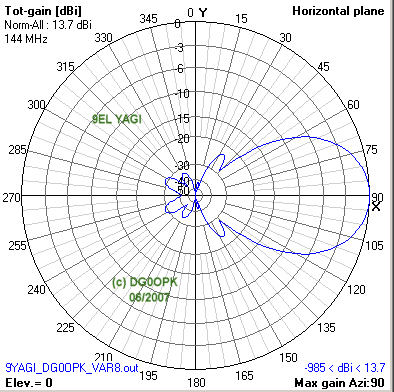
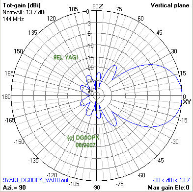
the result was my new 9EL Design with 4.3m BOOM 11.5dBd Gain
simulation results of the single 9EL antenna:
| TYPE |
L |
GAIN |
FWD |
SIDELOBE |
BACK |
Tlos |
Ta |
G/T |
frequency |
remarks |
| DG0OPK_9EL |
2.06 |
11.46 |
182.98 |
49.80 |
2.07 |
4.81 |
239.68 |
-10.19 |
144.0 MHz |
|
| DG0OPK_9EL |
2.06 |
11.53 |
183.23 |
49.35 |
1.54 |
5.06 |
239.29 |
-10.11 |
144.5 MHz |
|
| DG0OPK_9EL |
2.06 |
11.57 |
182.79 |
50.41 |
2.02 |
5.12 |
240.30 |
-10.09 |
145.0 MHz |
|
| DG0OPK_9EL |
2.06 |
11.55 |
173.08 |
54.96 |
4.21 |
4.99 |
245.82 |
-10.20 |
145.8 MHz |
						L    		= Length in Wavelengths
						FWD 	 	= Forward Lobe Noise Temperature
						SIDELOBE	= Sidelobe Noise temperature
						BACK 		= Antenna Noise made from backside lobe
						Gain 		= Gain in dBd of antenna (without losses)
						Tlos 		= The internal resistance of the antenna in degrees Kelvin (high losses means critical design)
						Ta  		= The total temperature of the antenna in degrees Kelvin. This
			       		  			  includes all the side lobes, rear lobes and internal resistance of the antenna.
						G/T  		= Figure of merit used to determine the receive capability of the antenna
      		 			  			  (Ga + 2.15) - (10*log Ta). The more positive figure the better.
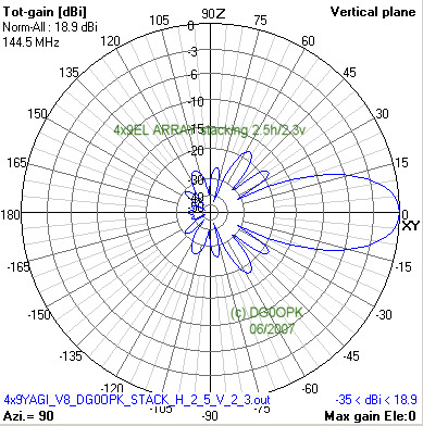
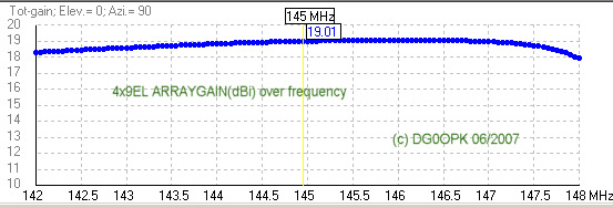
simulated horizontal and vertical pattern
simulated SWR over frequency

simulated impedance over frequency

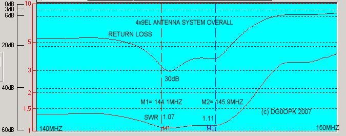
overall SWR measurement of the complete system
(on the antenna connector in my shack)
| Element |
Length |
Distance |
Diameter |
| reflector |
1024 |
0 |
5 |
| driven |
988 |
344 |
8 |
| director
1 |
962 |
577 |
5 |
| director
2 |
935 |
1071 |
5 |
| director
3 |
918 |
1703 |
5 |
| director
4 |
904 |
2411 |
5 |
| director
5 |
876 |
3050 |
5 |
| director
6 |
856 |
3666 |
5 |
| director
7 |
830 |
4300 |
5 |
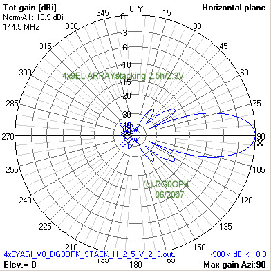
stacking parameters for an array of 2 x 2 for low sidelobes and moderate gain
(that could be my use in the city or in my home location)
calculatet noise temperature parameters for the
complete system
(Tsky=200K,Tearth=1000K)
stacking
distance
H = 2.5m , V = 2.3mGain @ 144 MHz = 16.75dBd (18.9dBi)
forward noise temperature
of the system @ 144MHz: 192.29K
sidelobe noise
temperature @ 144 MHZ:
22.52K
backside lobe noise
temperature @ 144 MHZ:
0.99K
loss
temperature @ 144 MHZ:
4.7K
overall antenna noise temperature @ 144 MHz: ca. 220K
G/T value calculations (using Tant by YT1NT, and tnx for help from Boban YU7XL)
| frequency | gain |
noise temperature (without
losses) |
G/T value |
| 144.0
MHz |
18.90dBi |
217.1 K |
-4.47dB |
| 144.5
MHz |
18.98dBi |
215.3 K |
-4.35dB |
| 145.0
MHz |
19.03dBi |
215.4 K |
-4.30dB |
| 145.8
MHz |
19.06dBi |
218.1 K |
-4.33dB |
stacking
parameters
for an array of 2 over 2 for maximal gain
stacking distance H = 2.95m , V = 2.55m
Gain @ 144 MHz = 17.5dBd (19.7dBi)
forward noise temperature
of the system @ 144MHz: 187.52K
sidelobe noise temperature @ 144 MHz:
36.86K
loss temperature @ 144 MHz: 4.78K
overall antenna noise temperature @ 144 MHz: ca. 230K
G/T value regarding to VE7BQH chart : -3.96dB
ADDITIONAL INFORMATION:
IN 2009 THE ANTENNAS WERE RECALCULATED BY VE7BQH
USING THE NEC4 ENGINE.
I CHANGED THE STACKING OF THE ANTENNAS TO 2.8 x 2.8m
THE SYSTEM GAIN IS NOW AROUND 17.3dB AND THE NOISE TEMPERATURE
IS AROUND 230K. THE VE7BQH CALCULATED G/T VALUE IS -4.16 dB.
Special Note:
This design is the work on many simulations and measurements over some month.
The mechanical work costs a lot of money and time of my friend Pit DM2CKK (sk).
Special thanks also to Karsten DM2CT and Jens DD5JE.
Distribution and publishing of these data and information is permited ONLY
for radioamateur purposes and construction.
Use of these information and data for any commercial purposes is strictly prohibited
without the written authorization of the author.
update: 24.March 2016
After more of 6 years operating with the system (nearly unchanged since 2012)
I re-measured the antenna parameters using my VNWA3 and all looks very well.
(I worked now over 100 DXCC on 2m and over 750 INITS on EME with my homemade system)
return loss @ 144.1 MHz > 35dB (SWR 1.03)
return loss @ 145.1 MHz ca. 25dB (SWR 1.11)
return loss @ 146 MHz > 27dB (SWR 1.09)
overall return loss/SWR measurement of my 4x2WL EME antenna system (2016)

If you need more information write me an email ....

last change: 24.march 2016 (DG0OPK)