MY NEW LOW NOISE AND WIDEBAND 4x8EL EME ANTENNA SYSTEM
my goal for this work:
WSJT from Joe Taylor K1JT made it possible to work also EME with small antennas and low power.
Thats why I decided in december 2005 to design an optimized antenna system for my purposes.
For weak signal operation my needs are the following for an optimzed antenna system:
1. good gain
2. low noise to prevent man made noise from monitors and computers
(low sidelobes,low TVI)
3. moderate bandwith for use in bad wheater (snow,ice) and also for SAT work
4.easy handling (because of not to big & complex mechanical construction)
5.payable material
So i started my work and analyzed....to find
the optimal solution for my purpose
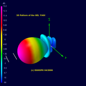
the result was my new 8EL Design with 3.62m BOOM 11dBd Gain
(many thanks for the help and conversation with Steffen DD0VF and Pop YU7EF)
simulation results of the single 8EL antenna:
| TYPE |
L |
GAIN |
FWD |
SIDELOBE |
BACK |
Tlos |
Ta |
G/T |
frequency |
remarks |
| DG0OPK_8EL |
1.74 |
10.98 |
177.17 |
66.84 |
2.73 |
4.67 |
251.52 |
-10.88 |
144.0 MHz |
|
| DG0OPK_8EL |
1.74 |
11.03 |
176.85 |
67.31 |
3.51 |
4.65 |
252.33 |
-10.84 |
144.5 MHz |
|
| DG0OPK_8EL |
1.74 |
11.04 |
175.83 |
69.30 |
5.34 |
4.76 |
255.23 |
-10.88 |
145.0 MHz |
|
| DG0OPK_8EL |
1.74 |
10.99 |
173.08 |
75.34 |
8.99 |
6.47 |
263.89 |
-11.08 |
145.8 MHz |
						L    		= Length in Wavelengths
						FWD 	 	= Forward Lobe Noise Temperature
						SIDELOBE	= Sidelobe Noise temperature
						BACK 		= Antenna Noise made from backside lobe
						Gain 		= Gain in dBd of antenna (without losses)
						Tlos 		= The internal resistance of the antenna in degrees Kelvin (high losses means critical design)
						Ta  		= The total temperature of the antenna in degrees Kelvin. This
			       		  			  includes all the side lobes, rear lobes and internal resistance of the antenna.
						G/T  		= Figure of merit used to determine the receive capability of the antenna
      		 			  			  (Ga + 2.15) - (10*log Ta). The more positive figure the better.
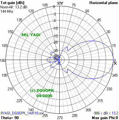
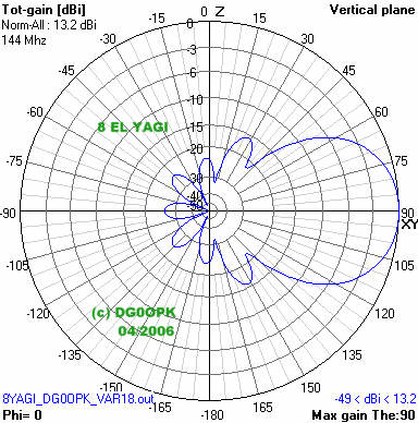
simulated horizontal and vertical pattern
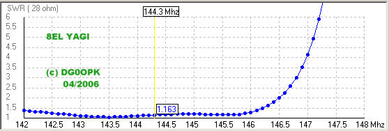
simulated SWR over frequency
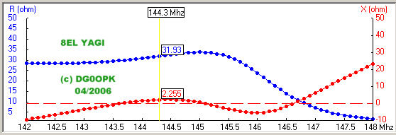
simulated impedance over frequency
(with Vectronics SWR-584B antenna analyzer and phasing line)
| frequency |
impedance |
SWR |
| 140 |
46+j16 |
1:2.1 |
| 141 |
38+j17 |
1:1.8 |
| 142 |
35+j11 |
1:1.5 |
| 143 |
36+j0 |
1:1.3 |
| 144 |
41+j0 |
1:1.1 |
| 145 |
48+j4 |
1:1.1 |
| 146 |
46+j0 |
1:1.1 |
| 147 |
37+j15 |
1.1.7 |
(with Vectronics SWR-584B antenna analyzer and phasing line)
| frequency | ANTENNA 1 SWR |
ANTENNA 2 SWR |
ANTENNA 3 SWR |
ANTENNA 4 SWR |
| 142 |
1:1.3 |
1:1.3 |
1:1.4 |
1:1.4 |
| 143 |
1:1.2 |
1:1.2 |
1:1.3 |
1:1.2 |
| 144 |
1:1.1 |
1:1.2 |
1:1.2 |
1:1.1 |
| 145 |
1:1.1 |
1:1.2 |
1:1.2 |
1:1.2 |
| 146 |
1:1.0 |
1:1.2 |
1:1.1 |
1:1.1 |
| 147 |
1:1.6 |
1:1.5 |
1:1.6 |
1:1.6 |
mechanical sizes for the elements
| Element |
Length |
Distance |
Diameter |
| reflector |
1024 |
0 |
5 |
| driven |
988 |
344 |
8 |
| director
1 |
962 |
577 |
5 |
| director
2 |
935 |
1071 |
5 |
| director
3 |
918 |
1703 |
5 |
| director
4 |
904 |
2411 |
5 |
| director
5 |
876 |
3050 |
5 |
| director
6 |
830 |
3616 |
5 |
mechanical sizes for the elements
| Element |
Length |
Distance |
Diameter |
| reflector |
1024 |
0 |
4 |
| driven |
988 |
344 |
8 |
| director
1 |
966 |
577 |
4 |
| director
2 |
940 |
1071 |
4 |
| director
3 |
923 |
1703 |
4 |
| director
4 |
910 |
2411 |
4 |
| director
5 |
882 |
3050 |
4 |
| director
6 |
838 |
3616 |
4 |
the first array is up in our portable location in jo50an and working fine (click for picture)
the second array is up in my home location in jo50gq (since 19.feb.2007)
stacking parameters for an array of 2x 2 for low sidelobes and moderate gain
(that could be my use in the city or in my home location)
calculatet noise temperature parameters for the
complete system
(Tsky=200K,Tearth=1000K)
stacking
distance
H = 2.3m , V = 2.3mGain @ 144 MHz = 16.18dBd (18.43dBi)
forward noise temperature
of the system @ 144MHz: 187.8K
sidelobe noise
temperature @ 144 MHZ:
35.16K
backside lobe noise
temperature @ 144 MHZ:
2.36K
loss
temperature @ 144 MHZ:
4.52K
overall antenna noise temperature @ 144 MHz: ca. 230K
G/T value calculations (using Tant by YT1NT, and help from Boban YU7XL)
| frequency | gain |
noise temperature (without
losses) |
G/T value |
| 144.0
MHz |
18.43dBi |
224.2K |
-5.08
dB |
| 144.5
MHz |
18.50dBi |
223.8K |
-5.00
dB |
| 145.0
MHz |
18.54dBi |
225.0K |
-4.99
dB |
| 145.8
MHz |
18.56dBi |
231.8 K |
-5.09
dB |
stacking parameters for an array of 2 over 2 for maximal gain (thats the use on the /portable location)
stacking distance H = 2.8m , V = 2.5m
Gain @ 144 MHz = 17dBd (19.15dBi)
forward noise temperature
of the system @ 144MHz: 182.83K
sidelobe noise temperature @ 144 MHz:
49.41K
loss temperature @ 144 MHz: 4.71K
overall antenna noise temperature @ 144 MHz: ca. 240K
G/T value regarding to VE7BQH chart : -4.65dB
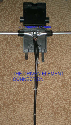
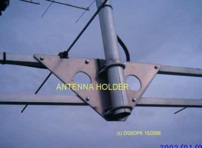
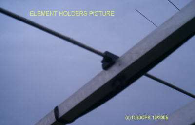
mechanical details
feed lines,driven element connection,antenna holder,element holder
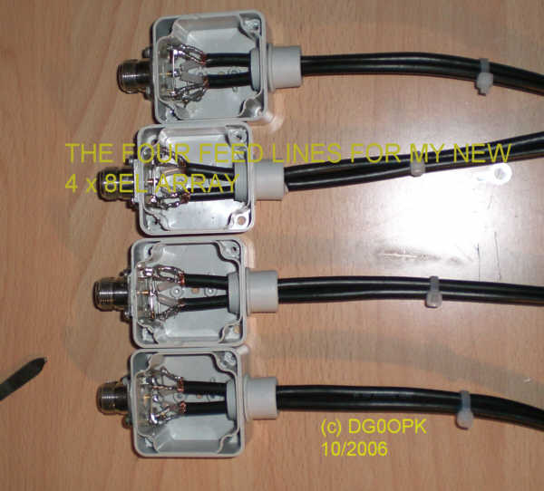
IF YOU WANT TO USE HIGHER POWER ... USE 75 OHM TEFLON CABLES FOR THE FEEDLINE.
(for my purposes QRP < 200W at the single antenna in a group of 4 , RG59 will do it)
Special Note:
This design is the work on many simulations and measurements over some month.
The mechanical work costs a lot of money and time of my friend Pit DM2CKK.
Special thanks also to Karsten DM2CT and Jens DO6JE.
Distribution and publishing of these data and information is permited ONLY
for radioamateur purposes and construction.
Use of these information and data for any commercial purposes is strictly prohibited
without the written authorization of the author.
if you are interested in some special parts or complete antennas write me an email ....

last change: 27.june 2007 (DG0OPK)